CIV102 aid sheet
This page may not display correctly. You can find a PDF here.
Appendices
Look up the following properties in the Appendices:
- Material
- $E$, $\sigma_y$, $\sigma_{ult}$, and $\sigma_{y,c}$
- HSS
- $A$, $I$, and $r$
- Steel wide flange beams
- $A$, $I_x$, $r_x$, $I_y$, and $r_y$
- Strong axis when placed like an “I”
- Unit conversions
- Areas and centroids of common shapes (included in this aid sheet)
- Common Canadian reinforcing bars
- $A_S$
Sign Convention
State the sign convention for every question.
Below is the sign convention for all parts in this aid sheet. Since counter-clockwise is the positive direction of rotation, a smiling beam has a positive bending moment diagram that is, in contrast, below the x-axis and vice versa for a frowning beam.

Formulas
Physics
\[\begin{cases} \vec{M}=\vec{r}\times\vec{F}\text{ (bending moment)}\\ k=\frac{EA}{L_0}\text{ (spring constant)}\\ w_n=\sqrt{\frac{k}{m}}\text{ (natural angular frequency)}\\ f_n=\frac{w_n}{2\pi}=\frac{1}{2\pi}\sqrt{\frac{k}{m}}\text{ (natural frequency)}\\ T_n=\frac{1}{f_n}\text{ (natural period)} \end{cases}\]Strain-stress Theory
Hooke’s law:
\[\begin{cases} \sigma=\frac{F}{A}=E\epsilon\text{ (stress)}\\ \epsilon=\frac{\Delta L}{L_0}\text{ (strain)}\\ \end{cases}\]The strain energy theory applies to both axial and shear forces.
\[\begin{cases} U=\int\sigma d\epsilon\text{ (energy density)}\\ W=UV_0\text{ (work)} \end{cases}\]Cross-section
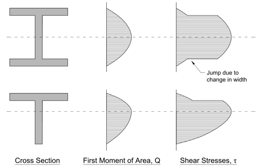
\[\begin{cases} \bar{y}=\frac{1}{A}\sum^n_{i=1}y_iA_i\text{ (centroidal axis)}\\ I=\sum^n_{i=1}I_i+A_id_i^2\text{ (moment of inertia)}\\ Q(y)=\int_0^yy\text{d}A=\int_y^{y_{max}}y\text{d}A=\sum A_id_i\text{ (first moment of area)} \end{cases}\]- $y$: height of an axis from the very bottom
- $d$: distance from an axis to the centroidal axis
- $y_{max}$: total height of the cross-section
Moments of inertia of simple shapes are given below.
\[I= \begin{cases} \frac{bh^3}{12}\text{ (rectangle)}\\ \frac{\pi r^4}{4}\text{ (circle)} \end{cases}\]$Q_{max}=Q(\bar{y})$ is calculated by:

Note that when calculating $Q$ at a given height, we only select regions that are above/below the given axis, but $d$ is still the distance from the centroid of the selected regions to the centroidal axis. When calculating $Q$ for complex shapes, if it is a hollow shape, we could use the whole region minus the empty region:
\[Q=A_1d_1-A_2d_2\]Shear Stress Distribution
Just in case there is a question about the shear stress distribution, here is a simple example.
Exam
Question 1: Truss Bridge Analysis
Solving
- Solve for reaction forces
- Check $\sum F_x=0$ and $\sum F_y=0$
- Identify zero members from T-shape joints
- Start with the joint with the fewest forces
- Propagate to all joints
- In the end, forces sum up to zero

All parts of the bridge must be at equilibrium.
\[\sum F_x=\sum F_y=\sum M=0\]If a member pushes both ends, like <--->, then the member is in compression. If a member pulls both ends, like >---<, then it’s in tension.
Vertical Displacement
- Replace all applied loads with only a single virtual load $P^\prime=1\text{ kN}$ at the joint of interest (the joint of which we are asked to calculate the displacement)
- Solve the bridge again for virtual internal forces $F^\prime$
- Use a table to sum up the virtual work, which is the displacement
- Convert kN to N
Either of the following two tables can be used to calculate the displacement.
| Member | $F\text{ (kN)}$ | $A\text{ (mm}^2\text{)}$ | $L_0\text{ (mm)}$ | $\Delta L\text{ (mm)}$ | $F^\prime\text{ (kN)}$ | $W\text{ (J)}$ |
|---|---|---|---|---|---|---|
| INPUT | INPUT | INPUT | INPUT | $1000\frac{FL_0}{EA}$ | INPUT | $F^\prime\Delta L$ |
| Member | $F\text{ (kN)}$ | $A\text{ (mm}^2\text{)}$ | $L_0\text{ (mm)}$ | $\sigma\text{ (MPa)}$ | $\epsilon\text{ (}\frac{\text{mm}}{\text{mm}}\text{)}$ | $\Delta L\text{ (mm)}$ | $F^\prime\text{ (kN)}$ | $W\text{ (J)}$ |
|---|---|---|---|---|---|---|---|---|
| INPUT | INPUT | INPUT | INPUT | $1000\frac{F}{A}$ | $\frac{\sigma}{E}$ | $L_0\epsilon$ | INPUT | $F^\prime\Delta L$ |
Natural Frequency
- Determine which model to use
- Plug in the vertical displacement
Forced Damping
- Determine the parameters
- Calculate $DAF$
- Calculate the maximum amplitude $P_{max}$
- $f$: forced oscillation frequency
- $\beta$: damping ratio
When the bridge is forced to oscillate with an amplitude of $P_A$ (in kN), the maximum amplitude is given by:
\[P_{max}=P+P_A\cdot DAF\]- $P$: originally applied load
Safe Design
Evaluation:
- Solve the cross-section to get $A$ and $I$
- $I$ is usually something $\times 10^{6\sim7}\text{ mm}^4$
- Calculate $r$
- Check the radius of gyration
- Check yielding
- Check buckling
Design:
- Calculate minimum $r$, $A$, and $I$
- Pick an HSS from Appendix B
The critical load for buckling, also known as the Euler load, $P_e=\frac{\pi^2EI}{L^2}$, and the radius of gyration is $r=\sqrt{\frac{I}{A}}$.
Question 2: Beam Bridge Analysis
Solving
- Solve for reaction forces
- Check $\sum F_x=0$
- Draw the SFD
- Left-to-right, kN over m
- Draw the BMD
- Left-to-right, kN$\cdot$m over m
- Positive down, negative up
- Solve the cross-section for $\bar{y}$ and $I$
- $I$ is usually something $\times 10^{6\sim7}\text{ mm}^4$
- Calculate $EI$
- N$\cdot$mm$^2$
- Find the deflection
- The area on the SFD is $10^6$ times larger than the label value
- The area on the BMD is $10^9$ times smaller than the label value
We can solve the displaced shape using Moment Area Theorems (MAT).
\[\begin{cases} \phi=\frac{M}{EI}\text{ (curvature)}\\ \Delta\theta_{AB}=\theta_B-\theta_A=\int_A^B\phi(x)dx\text{ (displaced angle, MAT 1)}\\ \delta_{DT}=\int_D^Tx\phi(x)dx\text{ (displacement, MAT 2)} \end{cases}\]
The displacement $\delta_{DT}$, which is the difference in height at point D between the tangent line drawn from point T and the actual y-coordinate, can be further simplified as:
\[\delta_{DT}=\bar{x}_{DT}\int_D^T\phi(x)dx=\frac{\bar{x}_{DT}}{EI}\int_D^TM(x)dx\]- $\bar{x}_{DT}$: horizontal distance from the centroid of the area to point D

When finding the deflection, there are three (3) possible cases:
- Known horizontal tangent due to support: Find the deflection of the point of interest from the support condition
- Known horizontal tangent due to symmetry: Find the deflection of the point of interest from the point of interest
- No known horizontal tangent: Find the deflection of support C from the tangent drawn from the other support A. Find the deflection of the point of interest from support A. Use similar triangles to relate them together. To calculate the deflection of the support from A, we have $\theta_A=\frac{\delta_{CA}}{L}$.
Special Case: One End is Free
When one end of the beam is free, the other end must have a support that provides a bending moment. In this case, start drawing the BMD from the free end to the support because the support will have a non-zero bending moment.
Stresses
- Determine the maximum moment
- Convert the moment to N$\cdot$mm
- Calculate $\frac{M_{max}}{I}$
- Convert kN$\cdot$m ($10^6$) or kN$\cdot$mm ($10^3$) to N$\cdot$mm
- Determine the concavity at the point of the maximum moment
- Calculate the flexural stresses
- If concave up, $\sigma_{compression}=\sigma_{top}$ and $\sigma_{tension}=\sigma_{bottom}$
- If concave down, $\sigma_{compression}=\sigma_{bottom}$ and $\sigma_{tension}=\sigma_{top}$
- Solve the cross-section for $Q_{max}$ and $b_{min}$
- Calculate the shear stress
- Convert kN to N
Flexural
Navier’s equation:
\[\sigma=\frac{My}{I}\]Usually we are only interested in the top and bottom axial stresses.
\[\begin{cases} \sigma_{top}=\frac{M(y_{max}-\bar{y})}{I}\\ \sigma_{bottom}=\frac{M\bar{y}}{I} \end{cases}\]- $\phi>0,M>0$: smile shape
- $\sigma_{compression}=\sigma_{top}$
- $\sigma_{tension}=\sigma_{bottom}$
- $\phi<0,M<0$: frown shape
- $\sigma_{compression}=\sigma_{bottom}$
- $\sigma_{tension}=\sigma_{top}$
Shear
Jourawski’s equation:
\[\tau=\frac{VQ}{Ib}\]Usually we are only interested in the maximum shear stress, therefore, we pick $Q_{max}$ and $b_{min}$.
Safe Design
For a beam bridge to be safe, all factors of safety must be at least greater than 1. FOS for yielding is 2 and for buckling is 3.
\[\begin{cases} FOS=\frac{\text{Capacity}}\text{ (factor of safety)}\\ P_{crit}=FOS(P=1\text{ kN})=x\cdot FOS(P=x)\text{ (maximum load in kN)} \end{cases}\]For a concave-up (smiling) beam bridge:
\[\begin{cases} FOS_{compression}=\frac{\sigma_{compression}^\prime}{\sigma_{top}}\ge3\\ FOS_{tension}=\frac{\sigma_{tension}^\prime}{\sigma_{bottom}}\ge2\\ FOS_{shear}=\frac{\tau^\prime}{\tau}\ge2\\ FOS_{glue}=\frac{\tau_{glue}^\prime}{\tau_{glue}}\ge2 \end{cases}\]The applied glue stress is $\tau_{glue}=\frac{VQ(y_{glue})}{Ib_{glue}}$.
Question 3: Plate Beam Analysis
This section is in addition to Question 2: Beam Bridge Analysis.
Plate Buckling
- Determine the parameters
- Calculate $\frac{\pi^2E}{12(1-\mu^2)}$
- Calculate $(\frac{t}{b})^2$
- Calculate the stresses
- Calculate the factors of safety
| Failure Mode | Failure Condition |
|---|---|
| Buckling of the compressive flange between the webs | $\sigma=4\frac{\pi^2E}{12(1-\mu^2)}(\frac{t}{b})^2$ |
| Buckling of the tips of the compressive flange | $\sigma=0.425\frac{\pi^2E}{12(1-\mu^2)}(\frac{t}{b})^2$ |
| Buckling of the webs due to flexrual stresses | $\sigma=6\frac{\pi^2E}{12(1-\mu^2)}(\frac{t}{b})^2$ |
| Shear buckling of the webs | $\tau=5\frac{\pi^2E}{12(1-\mu^2)}((\frac{t}{h})^2+(\frac{t}{a})^2)$ |
- $t$: thickness
- $b$: unsupported base
- $h$: unsupported height
- $a$: length between stiffeners

All distances are from one centroidal axis to another centroidal axis. In the diagram above, there is no horizontal support so $h$ is just the height of the web.
$b_3$ is the distance from the top (or the centroidal axis of the top horizontal support) to the centroidal axis of the cross-section.
Safe Design
For a beam bridge to be safe, all factors of safety must be at least greater than 1. FOS for yielding is 2 and for buckling is 3.
\[\begin{cases} FOS_{plate\_buckling}=\frac{\sigma_{plate\_buckling}^\prime}{\sigma_{top}}\ge3\\ FOS_{shear\_buckling}=\frac{\tau_{shear\_buckling}^\prime}{\tau}\ge3 \end{cases}\]Question 4: Reinforced Concrete
Solving
- Determine parameters $f_c^\prime$, $A_S$, $b$, and $d$
- Calculate $f_t^\prime$, $E_C$, $n$, and $\rho$
- Calculate $k$ and $j$
- $k<1,j<1$
- Calculate $kd$ and $jd$
- $A_S$: area of the steel reinforcements
- $b$: width of the cross-section
- $d$: distance from the top/bottom edge to the centroidal axis of the opposing reinforcement bars
For example, if it says 6-25M bars, then $A_S=6\times 500\text{ mm}^2$, where $500\text{ mm}^2$ is given in Appendix G.

The Young’s modulus of reinforcing steel is $E_S=2\times 10^5\text{ MPa}$, and the yield strength is $f_y=400\text{ MPa}$.
\[\begin{cases} k=\sqrt{(n\rho)^2+2n\rho}-n\rho\\ j=1-\frac{k}{3} \end{cases}\]$k$ and $j$ are scaling factors such that:
- $kd$: distance from the extreme compression fiber to the neutral axis
- $jd$: vertical distance between the compressive and tensile forces, also known as the flexural lever
If the values of $k$ and $j$ are unknown, let $k=\frac{3}{8}$ and $j=\frac{7}{8}$.
Stresses
- Draw the SFD
- Left-to-right, kN over m
- Draw the BMD
- Left-to-right, kN$\cdot$m over m
- Positive down, negative up
- Determine the maximum moment
- The moment is $10^6$ times larger than the label value
- Calculate the flexural stresses
- Determine the maximum shear force
- Calculate the shear stress
Flexural
\[\begin{cases} f_S=\frac{M}{A_Sjd}\text{ (reinforcement stress)}\\ f_C=\frac{k}{1-k}\cdot\frac{M}{nA_Sjd}\text{ (concrete stress)} \end{cases}\]We can simplify $f_C=\frac{k}{n(1-k)}f_S$.
Shear
\[\begin{cases} v=\frac{V}{b_wjd}\text{ (shear stress)}\\ V^\prime=V_C^\prime+V_S^\prime\text{ (shear strength)} \end{cases}\]- $b_w$: web width
- $V_C^\prime$: concrete shear strength
- $V_S^\prime$: reinforcement shear strength

$A_v$ is the effective area of the stirrups, where $A_{bar}$ is given in Appendix G.

Safe Design
Partial FOS for concrete is 0.5 and for steel is 0.6.
Evaluation:
- Check the flexural stresses
- Check the shear stress
- Check the shear strength
Design:
- Choose $A_S\ge\frac{M}{0.6f_yjd}$ with assumptions that $k=\frac{3}{8}$ and $j=7/8$
- Calculate the actual values of $k$ and $j$
- Calculate the actual value of $jd$
- Check if the design is safe
- If not, pick a larger value for $A_S$
- Check if $V\ge0.5V_{crit}$
- If not, increase the size of the cross-section
- Check if the shear force can be resisted by the concrete alone
- $V^\prime=0.5V_C^\prime=\frac{115\sqrt{f_C^\prime}}{1000+0.9d}b_wjd$
- If true, the design is complete
- Add the minimum amount of shear reinforcement (two (2) legs)
- $s\le\frac{A_vf_y}{0.06\sqrt{f_C^\prime}b_w}$
- $s\le600\text{ mm}$
- $s\le0.63d$
- Check if the shear capacity is large enough
- $V^\prime=0.09\sqrt{f_C^\prime}b_wjd+0.6\frac{A_vf_yjd}{s}\cot35^\circ$
- If true, the design is complete
- Decrease the spacing
The yield moment is given by:
\[M_{yield}=A_Sf_yjd\]The critical shear force at which the concrete will crush is:
\[V_{crit}=0.25f_C^\prime b_wjd\]For a concrete to be safe, all the following conditions must be met:
\[\begin{cases} f_C<0.5f_C^\prime\\ f_S<0.6f_y\\ v<0.25f_C^\prime\\ V<V^\prime\le V_{crit} \end{cases}\]The first condition is equivalent to $A_S\ge\frac{M}{0.6f_yjd}$.
For shear design, we pick $V^\prime=0.5V_C^\prime+0.6V_S^\prime\le0.5V_{crit}$.
- If $V\ge0.5V_{crit}$, the cross-section needs to be enlarged
- If $V\ge0.5V_C^\prime$, minimum shear reinforcements (two (2) legs) need to be added
- If $V\ge0.5V_C^\prime+0.6V_S^\prime$, the spacing needs to be decreased to: \(s=\frac{0.6A_vf_yjd\cot35^\circ}{V-0.09\sqrt{f_C^\prime}b_wjd}\)
In the CSA/ACI standards, the minimum shear reinforcement must be enclosed.
Prestressed Concrete
\[\begin{cases} \sigma_{top}=-\frac{P}{A}-\frac{M(y_{max}-\bar{y})}{I}\\ \sigma_{bottom}=-\frac{P}{A}+\frac{M(y_{max}-\bar{y})}{I} \end{cases}\]If the tendon is eccentric (offset from the center by a distance $e$), the stresses are:
\[\begin{cases} \sigma_{top}=-\frac{P}{A}+\frac{Pe(y_{max}-\bar{y})}{I}-\frac{M(y_{max}-\bar{y})}{I}\\ \sigma_{bottom}=-\frac{P}{A}-\frac{Pe(y_{max}-\bar{y})}{I}+\frac{M(y_{max}-\bar{y})}{I} \end{cases}\]If you found this useful, please cite this as:
Fu, Tianhao (Dec 2025). CIV102 aid sheet. Tianhao Fu. https://atatc.me.
or as a BibTeX entry:
@article{fu2025civ102-aid-sheet,
  title   = {CIV102 aid sheet},
  author  = {Fu, Tianhao},journal = {Tianhao Fu},
  year    = {2025},
  month   = {Dec},
  url     = {https://atatc.me/blog/2025/civ-aid/}
}
Enjoy Reading This Article?
Here are some more articles you might like to read next: